2019年6月10日星期一

How to Calculate Excavator Bucket Capacity

How to Calculate Excavator Bucket Capacity

Bucket capacity is a measure of the maximum volume of the material that can be accommodated inside the bucket of the backhoe excavator. Bucket capacity can be either measured in struck capacity or heaped capacity as described below:
excavator long arm
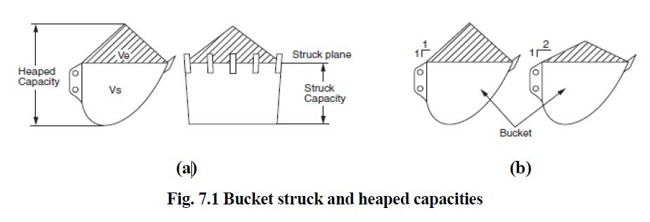
Struck capacity is defined as: The volume capacity of the bucket after it has been struck at the strike plane. The strike plane passes through the top back edge of the bucket and the cutting edge as shown in Fig. 7.1 (a). This struck capacity can directly be measured from the 3D model of the backhoe bucket excavator.
On the other hand the calculation of the heaped capacity is done by following the standards. Globally two standards used to determine the heaped capacity, are: (i) SAE J296: “Mini excavator and backhoe bucket volumetric rating”, an American standard (Mehta Gaurav K., 2006), (Komatsu, 2006) (ii) CECE (Committee of European Construction Equipment) a European standard (Mehta Gaurav K., 2006), (Komatsu, 2006).
Heaped capacity is defined as: The sum of the struck capacity plus the volume of excess material heaped on the bucket at a 1:1 angle of repose (according to SAE) or at a 1:2 angle of repose (according to CECE), as shown in the Fig. 7.1 (b). This in no way implies that the hoe must carry the bucket oriented in this attitude, or that all material will naturally have a 1:1 or 1:2 angle of repose.
As can be seen from the Fig. 7.1 the heaped capacity Vh can be given as:
Vh=Vs+Ve                             …. (7.1)
Where, Vs is the struck capacity, and Ve is the excess material capacity heaped either at 1:1 or at 1:2 angle of repose as shown in Fig. 7.1 (b).
Firstly, from Fig. 7.2 struck capacity Vs equation will be presented, then by using two methodologies SAE and CECE, two equations of excess material volume or capacity Ve will be presented from Fig. 7.2. Finally bucket heaped capacity can be found from equation (7.1).
excavator bucket capacity calculation
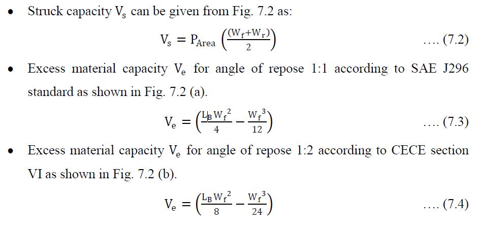
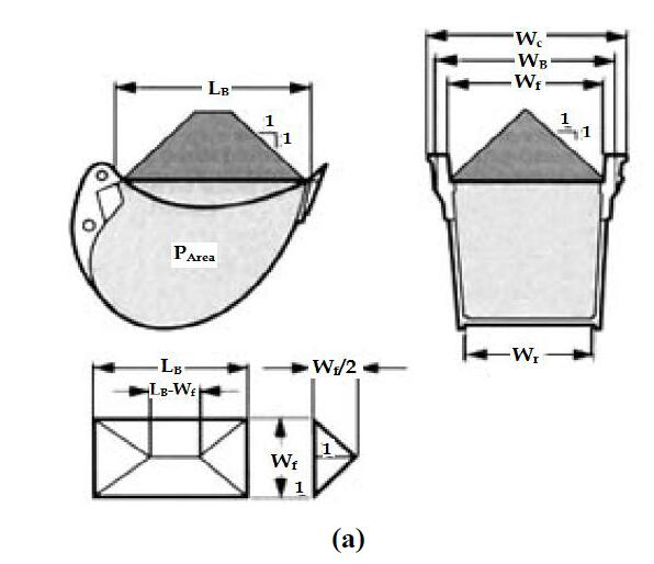
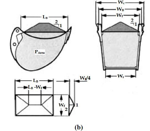
Fig. 7.2 Bucket capacity rating (a) According to SAE (b) According to CECE
  • The description of the terms used in Fig. 7.2 is as follows:
  • LB: Bucket opening, measured from cutting edge to end of bucket base rear plate.
  • Wc: Cutting width, measured over the teeth or side cutters (note that the 3D model of bucket proposed in this thesis is only for light duty construction work, so side cutters are not attached in our model).
  • WB: Bucket width, measured over sides of bucket at the lower lip without teeth of side cutters attached (so this will also not to be the important 108 parameter for the proposed 3D model of bucket as it does not contain any side cutters).
  • Wf: Inside width front, measured at cutting edge or side protectors.
  • Wr: Inside width rear, measured at narrowest part in the back of the bucket.
  • PArea: Side profile area of bucket, bounded by the inside contour and the strike plane of the bucket.
Fig. 7.3 shows the important parameters to calculate the bucket capacity for the proposed 3D model of bucket. The calculation done is based on SAE standard as this standard is globally acceptable and used.
excavator long arm
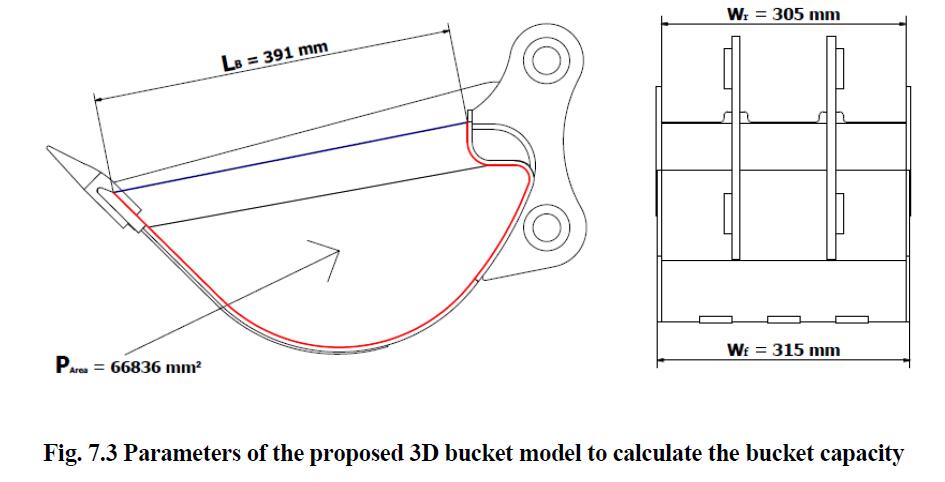
As can be seen from the left side of the Fig. 7.3 PArea is the area bounded by struck plane (blue line) and side protector (red curve), and it is 66836 mm2.
By using equations (7.1), (7.2) and (7.3) the bucket capacity for the proposed 3D backhoe bucket model comes out to be 0.02781 m3 = 0.028 m3.

2018年1月29日星期一

Heavy Duty standard boom arm and 1.1m3 rock bucket for DX225 CLA excavator

Heavy Duty standard boom arm and 1.1m3 rock bucket for DX225 CLA excavator

Heavy Duty Excavator Boom Arm (5.7m BOOM +2.4m ARM) reinforced for critical areas,  with additional hammer pipeline.  1.2MCBM Hardox Rock Bucket which cutting edge, side blades and wear strips made of Hardox 400 steel, rock teeth.
This boom arm and bucket configuration  suitable for mining and quarry jobsite.

2017年4月19日星期三

Orange Peel Grapple

Orange Peel Grapple

Application:

Excavator grapple for grabbing gravels,waste metals,industry waste,construction garbage daily rubbish.

Image of Orange peel grapple Grapple


Characteristic

  1. *Grapple pipes covered with steel cover
  2. *Cylinder also with steel protection cover
  3. *Tine is box structure that make grapple durable
  4. *Triangular reinforced plate welded for blade
  5. *Tips made by Hardox Material
  6. *Tine pin is oversized

Parameter

ModelVOPG-100VOPG-150VOPG-200VOPG-250VOPG-300
Weight(KG)570820108013202200
Max. Openning(mm)14001560183020002170
Capacity(M3)0.310.430.590.91.2
Height(mm)14701650178020302245
Tine44555
Excavator tonage10-1213-1516-2324-2728-33


Case

Material Handler fronts with clamshell bucket

Material Handler Boom

Application:

material handling boom arm fitted on excavator machine from 15 ton to 120 ton to lift bulk material with scrap grapple or carry sand with clamshell bucket.

Material Handler Boom image


Characteristics:

  • Twin / single under-slung cylinder fully exploit cylinder's force for material lifting.
  • Additional counterweight is available
  • Clamshell/orange peel grab/rock grapple is optional

Our product can well fit these excavator brand: KOMATSU,HITACHI, CATERPILLAR,SUMITOMO, HYUNDAI, KOBELCO, KATO, SANY,DAEWOO,VOLVO etc.

Material handling Boom case

2017年4月18日星期二

High quality clamshell bucket for excavator

Clamshell Bucket

Application:

Clamshell bucket for loading bulk material, or digging loose material, such as sand, etc

Characteristic

  1. Strong digging or grabbing force is ensured due to shell's openning and closing controled directly by hydraulic ram
  2. Especially suitable for working with telescopic dipper arm and material handler in a restricted working space.
  3. Heavy duty type or rotary one is optional

specification of clamshell bucket

Excavator (ton)Bucket CapacityWeight
(M3)Yard3(KG)(Lb)
6-100.60.785701257
11-160.81.057601676
17-2011.39001984
21-241.21.5711202469
25-301.41.8313502976
31-351.62.0916003527
36-401.82.3518504079
41-4522.6221504740

Pictures & Case of Clamshell bucket


2017年4月16日星期日

High reach demolition excavator

Browsing through various social media channels, I came across a number of worrying examples of how NOT to use specialist High Reach Demolition equipment. One such example led to the tragic loss of life, a high reach operator who I "suspect" made a fatal mistake... undercutting a building, which subsequently collapsed on top of the cab of the machine. Very sad and very concerning....
The variety and sheer quantity of alarming images that I saw, prompted me to share some of our management procedures, we use to ensure the safe use of this potentially hazardous equipment. These procedures have been developed and refined over the last 20 years of our extensive experience working with this equipment. We currently a variety of rigs which provide a diverse range of working configurations. Having said that some of our experience has been as a result of near misses and incidents on our own projects. The procedures implemented have ensured that these mistakes have not been repeated.
I hope that this post may help people when considering the safe use of this specialist method of demolition....
Generally check that all necessary experience, competencies and certification are in place relevant to the project in hand. This should include:- management, designers, supervision, operators, supporting staff to include the plant and equipment itself.
The risk profile directly correlates to the size of the building and therefore the size of the machine used. As each increases so do the risks of the operation.
Main points to consider (not intended to be everything)...
1 - Check that all possible methods of demolition are assessed and evaluated prior to concluding that High Reach Demolition is the correct method to select. Possible factors to consider....
  • Height - can High Reach equipment be used, if so what size plant is needed to reach and work safely, allowing for the necessary stand off? The HSE provide guidance in this area.
  • Access - can the equipment be delivered to site, once on site is there enough room for it to work?
  • Environment - proximity to other buildings, sensitive activities? Vibration, dust, noise etc.
  • Structure - section size of structural members? risk of premature collapse
  • Exclusion zone - safe area for plant to work and debris to fall?
  • Programme - timing of demolition, duration to suit school holidays, public transport not running, does the programme work?
We have demolished structures where we have deconstructed floor by floor, then used high reach demolition techniques, followed by explosive demolition all on the same building! In demolition the options are endless.
2 - If selected, ensure that the equipment proposed is the correct size to carry out the work. The machine will need to work safely with adequate reach and height. The safe working reach is not the same dimension as the machines maximum reach, we generally reduce the machines maximum reach taken from the spec sheet between 20-35% to calculate the safe working height for demolition. Although each project and set of circumstances will require a more detailed review to ensure all of the factors are considered before finally selecting the correct plant. So a narrow chimney is different to a deep high rise structure.
3 - Ensure that the equipment can safely carry the right demolition tool at the end of the high reach boom, this must be suited to the machine first and foremost and then secondly to the structure being demolished. The attachment will need to have the correct jaw appropriate for crushing, cracking or shearing, the right power and opening size to ensure the material can be demolished safely and efficiently. So heavy tall structures such as power stations may be within the machines reach, but the tool that is used at the end of the high reach boom may not demolish the building. The temptation is to put heavier tools on the end of machines that are simply not designed to carry them. This should of course should be avoided. Working within the guidelines set by the manufacturer is essential in this respect.
4 - Check the ground conditions typically over site slabs, ground make up, water table level, look generally for voids, basements and the like. This information should be collated by suitably qualified engineers in the form of a ground investigation report. The report should be issued to the Demolition Design Engineer typically a professionally qualified Civil or Structural Engineer who is responsible for all aspects of the demolition design on the project. Appropriate levels of Professional Indemnity insurance must be in place.
5 - Some of these machines weight over 200 tonnes, they have significant dead loads and very lively live loads! So it is essential that the area that the machine travels on and more importantly the area that the machine works from is treated in the same way as a piling rig. It is imperative that the Demolition Design Engineer ensures that the plant is stable at all times. The ground investigation report will be used to assess the need for any temporary works and then the design of such temporary works. Typically steel road plates and crane mats are used for access, engineered fill conforming to a recognised specification is used for the working platform for example crushed 6F2. If ramps are intended there use should be limited they should also form part of the temporary works design. Demolition debris that is not pulverised or crushed to 6F2 should not be used.
6 - Check the structure on site using a competent engineer to establish in detail the following:-
  • Type of structure - cast in-situ or steel frame, large panel etc.
  • Condition of the structure - defects, corrosion, cracks and general stability.
  • Trial pits for reinforcement details, connections, dimensions and sizes of structural components.
  • Refer this information to any existing as built information to ensure no immediate issues arise.
For some structures it may be necessary for temporary works to be designed and installed to facilitate the same demolition. This is particularly relevant for pre-cast concrete large panel high rise structures, that become very unstable when using High Reach Demolition techniques.
This I believe is one of the main problems with a lot of demolition projects generally and High Reach Demolition projects are no exception....
7 - Ensure that a suitably qualified, experienced structural or civil engineer has been central to the development of the demolition method statement, safe systems of work and overall sequence of the demolition to safely reduce the structure to the ground, safely without any premature collapse. That the working method and sequence is simply and clearly set out by whatever means to suit each company, so drawings, photos and text are common with the use of videos and 4D models now being used also. It is essential that the plan is effectively communicated to the site delivery team, that they understand the documents, and have been included in there development. All general site management procedures apply with regard to proposed changes, new information and contingency planning. Any new information gathered as the site works progress must be fed back to the Demolition Design Engineer to ensure that no unnecessary risks are taken. Any proposed changes to the working method and sequence must not proceed without being discussed, proposed and considered by the Demolition Design Engineer.
This post is not intended to be the absolute guide that covers every aspect of the process for High Reach Demolition or demolition generally. I may have missed some points that other people feel are equally if not more important than those I have listed. Please feel free to add thoughts, comments and personal experiences to this post to help educate us all so that we may prevent in the future more lives being lost.
If you would like further information the National Federation of Demolition Contractors have written guidance notes on the safe use of High Reach Demolition Rigs, as does the HSE.
author:Mark FCIOB, MIDE, AIExpE Managing Director - The Coleman Group - Specialist Demolition, Design, Engineering, Specialist Cutting, & Remediation

2016年6月27日星期一

19m excavator long reach attachment for pc400-7

In Jan. 2016, a valuable buyer from U.A.E. inquire about offer of 60ft Long Reach Attachment for their PC400-7 excavator, they need long reach attachment to carry out some long distance dredging and dredge work underwater.
After several rounds of discussion, we calculated and confirmed that  a set of 19m long reach boom stick suitable for their project and excavator, Considering of saving time in process of exchanging standard booms and long reach booms, we offered all necessary part: arm & bucket cylinder, a 1M3 bucket, linkage, hoses,and pins, customer just need to remove standard boom and install long booms and connecting hoses and cylinder.
the long reach boom can dig Max. forward reach 18.6m , Max. digging depth 13m underground.